Off-Site Distortion and Color Compensation of Underwater Archaeological Images Photographed in the Very Turbid Yellow Sea
Article information
Abstract
Underwater photographing and image recording are essential for pre-excavation survey and during excavation in underwater archaeology. Unlike photographing on land, all underwater images suffer various quality degradations such as shape distortions, color shift, blur, low contrast, high noise levels and so on. Outcome is very often heavily photographing equipment and photographer dependent. Excavation schedule, weather conditions, and water conditions can put burdens on divers. Usable images are very limited compared to the efforts. In underwater archaeological study in very turbid water such as in the Yellow Sea (between mainland China and the Korean peninsula), underwater photographing is very challenging. In this study, off-site image distortion and color compensation techniques using an image processing/analysis software is investigated as an alternative image quality enhancement method. As sample images, photographs taken during the excavation of 800-year-old Taean Mado Shipwrecks in the Yellow Sea in 2008-2010 were mainly used. Significant enhancement in distortion and color compensation of archived images were obtained by simple post image processing using image processing/analysis software (PicMan) customized for given view ports, lenses and cameras with and without optical axis offsets. Post image processing is found to be very effective in distortion and color compensation of both recent and archived images from various photographing equipment models and configurations. Merits and demerit of in-situ, distortion and color compensated photographing with sophisticated equipment and conventional photographing equipment, which requires post image processing, are compared.
1. INTRODUCTION
The author of The Bluffer’s Guide to Archaeology, Paul G. Bahn, made brief yet very powerful statements about underwater archaeology and it is introduced in training manuals for underwater archaeologists (Bahn, 2004; Viduka, 2012). “Excavating on land is hard enough, but some people like to make things extra difficult for themselves, and working underwater is the archaeological equivalent of standing up in a hammock” (Bahn, 2004). No one with swimming experience would doubt or argue about the statement.
In underwater and maritime archaeology, divers take images underwater for surveillances and during excavations. Remote-controlled underwater drones are also used occasionally (Pedros de Lima et al., 2020; Benjamin et al., 2019). Access to the archaeological sites is challenging for both divers and drones due to the relatively changeable water, water pressure, currents, waves, wind, temperature, obstructions, and often lacks visibility to make precise judgments and capture images. Capturing perfect images is generally very difficult. In turbid water, visibility is very limited due to light scattering and absorption by floating particles regardless of other conditions such as depth, current, waves and temperature.
Since the beginning of underwater photography in the 1850s by the pioneer William Bauer, it was already noticed that the proper acquisition of underwater photographs would require severe modifications to photographic equipment (Menna et al., 2016). In many underwater archaeology projects, consumer cameras in their own underwater camera housings, equipped with external strobe lights, are used by divers when diving conditions are met for diver’s safety (Menna et al., 2016). Water is a medium inherently different from air in terms of density. Seawater is nearly 800 times denser than air, and this influences the image formation underwater as the path of optical rays is altered (Menna et al., 2016; Reef2Reef, 2021; Stupar et al., 2012; HyperPhysics, 2021). Density of seawater is not constant through depth and is a function of temperature, salinity and pressure (Menna et al., 2016).
The shape of the viewport can be flat or a dome. For the flat port configuration, the field of view (FOV) narrows by 33% due to the refractive index difference between air (n = 1.0) and water (n = 1.3394 at salinity of 35 ppt (parts per thousand))(Reef2Reef, 2021). The angles of light incidence and refraction passing through a boundary between two different isotropic media, such as water, glass, or air can be calculated by Snell’s law (HyperPhysics, 2021; Jung et al., 2021). Advances in the field of underwater optical imaging, trends in emerging underwater imaging research and development are constantly introduced (Kocak et al., 2008).
During a survey of the Weihai Bay in 2017, the survey team noticed an unusual magnetic anomaly off the shore of Liugong Island, close to 500 meters off Liugong Island’s East village in Weihai Bay, East China’s Shandong Province. It resulted in the discovery of a Sunken 19 th century Chinese battleship in Yellow Sea (Global Times, 2019). The ironclad battleship Dingyuan, one of the flagship vessels of the Qing Dynasty’s (1644-1911) Beiyang Fleet, was sunk in the Yellow Sea during a battle with an invading Japanese fleet in February 1895. According to a research fellow at the National Center of Underwater Cultural Heritage and head of the survey team, they faced four major difficulties in underwater archaeological investigation. They are (1) difficulty in survey methods (2) the extremely unpredictable environment due to the constant strong waves, (3) the cold water temperature and depth and (4) poor visibility to determine the precise location of an object.
From 2008, shipwrecks were excavated in the opposite side of the Yellow Sea near Taean Mado island in the west coast of Korea. They were 800-year-old cargo ship during Goryeo Dynasty (NRIMCH, 2010; NRIMCH, 2011; Kim and Moon, 2011; Koh, 2014; Yang, 2011; Nam et al., 2010). Detailed excavation reports were published with underwater photographs during archaeological surveillance and excavation. From the excavation record keeping point of view, very poor visibility often in the range of 30 to 50 cm of the Yellow Sea made photographing and video recording extremely difficult (Jung et al., 2021; NRIMCH, 2011; Kim and Moon, 2011). Selected photographs, mostly taken through a fisheye lens with severe barrel distortion and color shift due to the suspended sediment and enhanced absorption of longer wavelength light, were used in the excavation reports (NRIMCH, 2011; Kim and Moon, 2011).
In this study, distortion and color compensation of archived underwater archaeological images photographed in the very turbid Yellow Sea during Taean Mado Shipwreck excavations from 2008 were revisited for distortion and color compensation using a customized image processing/analysis software (PicMan)(Jung et al., 2021; Kim et al., 2019; Yoo et al., 2019; Yoo and Yoo, 2021; Yoo, 2020; Yoo et al., 2021; Kim et al., 2019; Lee and Wi, 2021). The possibility and effectiveness of future off-site post processing applications of underwater archaeological photographs and video images were evaluated. The objectives of this study are to develop practical distortion and color compensation procedures for archived underwater photographs and video images and future underwater imaging activities without significant equipment change or investment.
2. EXCAVATION SITE OF TAEAN MADO SHIPWRECKS AND SELECTED PHOTOGRAPHS
2.1. Taean Mado Shipwreck Site
In 2007, two local fishermen reported a number of porcelain vessels they discovered during net fishing activities near Mado (Ma Island), Taean, Korea by chance (Koh, 2014). The location of the shipwreck is shown on a regional photograph (NASA, 2015) taken from the NASA’s Aqua satellite on February 24, 2015 in Figure 1 (NRIMCH, 2010; NRIMCH, 2011; Kim and Moon, 2011; Koh, 2014; Yang, 2011; Nam et al., 2010). In response to the fishermen’s report, an underwater survey was conducted by the National Research Institute of Maritime Cultural Heritage (NRIMCH), a branch of the Cultural Heritage Administration of the South Korean government (NRIMCH, 2010; NRIMCH, 2011). A visual reconnaissance of the seabed over an area of 200 m × 200 m led to the discovery of multiple shipwrecks. More than 60 pieces of porcelain vessels have been retrieved. Some of them were largely intact and undamaged. They were found to be nicely packed with straw wrappers, even with 800 years buried in the seabed. The first and second ships of the discovered shipwrecks were named after a neighboring island Mado and called Ship No. 1 and Ship No. 2. It was excavated by a team from NRIMCH between 2009 and 2010. The excavation of the shipwreck resulted in recovery of more than 300 porcelain vessels. Upon investigation of the cargo and their wooden tags, the cargo ship was headed to Gaegyeong, the capital of the Goryeo dynasty. The cargo tags of the Ship No. 1 and Ship No. 2 indicated the shipment was made around 1207-1208 and 1217, respectively (Kim and Moon, 2011; Koh, 2014; Yang, 2011). They were discovered about 800 years after being wrecked in the Yellow Sea.

Taean Mado Shipwreck site and swirls of color in the Yellow Sea photographed from NASA’s Aqua satellite on February 24, 2015 (NASA, 2015).
The point where Mado Ship 2 sank is about 400 m northeast of Mado, Taean, Korea. The average depth of the excavation site is about 5 m with a deviation of 5 m depending on the tide. In terms of the excavation environment of the shipwreck sites, the difference between tides is very large (average 484 cm and 299-668 cm in range) and the current is very fast (up to 20 cm/s) throughout the year. The high tide lasts an average of 3.5 hours and the low tide lasts 8.5 hours. All of these conditions make underwater excavation physically very difficult (NRIMCH, 2011).
2.2. The Yellow Sea
The Yellow Sea is a marginal sea of the Western Pacific Ocean. It is located between mainland China and the Korean Peninsula and named from its color (Wikipedia, 2021). It is often referred as the north-western part of the East China Sea. The region of Bohai Sea, Yellow Sea, and East China is one of the most turbid and dynamic ocean areas in the world. In the satellite image of the region, the brown area along China’s Subei Shoal (Figure 1) is turbid water, commonly seen in coastal regions. Shallow depths of water, tidal currents, and strong winter winds likely contributed to the mixing of sediment through the water. The Yellow Sea Warm Current in winter time might be responsible for the swirls in the image (NASA, 2015). Its name is descriptive of the phenomenon of turning its waters a golden yellow by fine sand grains from the northwest (annual Gobi Desert sand storms). It is one of four seas named after common color terms (the others being the Black Sea, the Red Sea and the White Sea)(Wikipedia, 2021). As the name suggested, the water is very turbid with yellowish-brown color. The visibility under water is very limited. Underwater photography is very challenging due to the turbid or murky nature of water.
Based on hydrodynamic measurement and analysis of suspended sediments in the Yellow Sea, Jinhae bay in the Korean Strait (Figure 1), suspended-sediment concentrations in the south-eastern Yellow Sea range from 5 to 100 mg/1 at the surface and 5 to 500 mg/1 at the bottom in waters that are 20-80 m deep during the summer to winter transition. The highest concentrations occur off the southwest tip of the Korean Peninsula and the lowest occur in the central part of the Korea Strait (Wells and Huh, 1984; Wells, 1988; Lee et al., 2006). These concentrations are 1 to 3 orders of magnitude higher than in “typical” shelf-depth waters in most other parts of the world. These high concentrations of suspended-sediment provide the opportunity for enormous sediment transport rates within this coastal mud stream, even under relatively weak currents. The abrupt termination of this inshore band of cold, turbid water as a turbidity front some 25-50 km offshore marks the seaward boundary of the high-transport zone (Wells and Huh, 1984; Wells, 1988; Lee et al., 2006).
Due to very high turbidity, the visibility under yellowish-brown water in the Yellow Sea is far less than 1 m. Typical ranges are 30 cm to 50 cm, even on a clear day with no waves. Photographing standard 1 m × 1 m grids for maritime heritage excavation sites under water is very challenging. A very wide view angle (180° in air) fisheye lens with an 8 mm focal length and a dome port camera housing is typically used even though it results in images with severe, unwanted barrel-shaped distortion. The effective view angle of the fisheye lens under water through the dome port housing is reduced to 130° (Jung et al., 2021).
While the most effective method for surveying underwater archaeological sites is visually identifying areas with relics or remains through diving surveys, underwater excavations often rely on geophysical equipment for surface inspections using marine acoustic geophysical survey equipment which is not significantly affected by underwater turbidity (Lee et al., 2021; Jung et al., 2017). It is difficult to obtain images in turbid water during underwater excavations. Furthermore, on-site diving is costly and time-consuming. The first underwater archaeological geophysical survey in South Korea was conducted on the Chilcheollyang seafloor (Figure 1) survey by the Cultural Heritage Administration in 1973. Under the Local Regulations on Methods and Procedures for Surface Surveying, 485 surveys of underwater archaeological sites were conducted from 2005 to 2019. So far, no ancient shipwrecks have been detected using marine geophysical survey equipment in South Korea (Jung et al., 2017).
2.3. Selected Underwater Photographs
More than 300 underwater photographs taken during the Mado Shipwreck No. 1 and No. 2 excavation projects from 2008 to 2010 (NRIMCH, 2010; NRIMCH, 2011) were selected for testing. Photography was mainly done with an 8 mm fisheye lens (8 mm F3.5 EX DG Circular Fisheye lens, Sigma Corporation, Japan) on a full frame camera (EOS-450D camera, Canon Inc., Japan) with a dome port made of optical glass with anti-diffused reflection coating (PDCH-450D for Canon EOS-450D Camera, Patima Underwater Engineering, Korea)(Jung et al., 2021). There is a mixture of photographs taken using an 8 mm fisheye lens with a dome port camera housing and a 15 mm fisheye lens with a dome port camera housing. It is almost impossible to capture the entire grid within the size of 1 m on each side in a single frame with a wide-angle 15 mm lens. Under water, the FOV decreases approximately 40% from the air due to the view angle limitation of the dome port camera housing. Photographs using a 15 mm fisheye lens is less distorted and no dark regions are visible from the four corners. Photographs taken through an 8 mm fisheye lens always show severe barrel shaped image distortion with black regions at four corners being easily identified. Underwater photographs before and after distortion and color compensation will be shown in the following section as example of experimental results in this study.
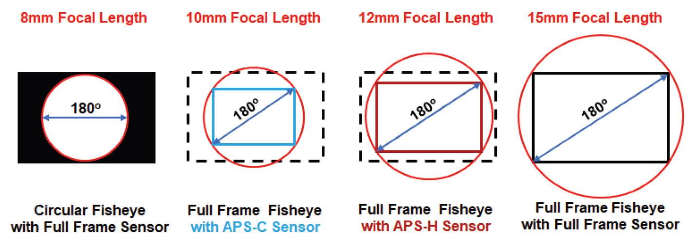
Using an 8-15 mm fisheye lens on cameras with different size sensor formats produces differing results. The resulting image also depends on the focal length settings. Only the circular fisheye lens with full frame sensor at 8 mm focal length allows the full circular fisheye option. Figure 2 illustrates the image circle coverage on various image sensor sizes over the focal length range. For a given camera, and more specifically, for a given image sensor, the 8-15 mm fisheye lens cannot provide 180 o FOV, even in air. When it comes to underwater photography, view port shape, distance between lens and view port also plays a significant role in the resulting images. Some images show black areas in the corners showing the FOV limit for specific photographic equipment and conditions. In the ideal case, the size and shape of the four black areas in the corner of the resulting images should be perfectly symmetrical. However, it is not usually the case for underwater photography. This is mainly due to slight misalignment in optical axes and focal points from different reasons such as defective design, improper assembly, deformation of the viewport under water and so on.
2.4. Image Processing/Analysis Software (PicMan)
A novel image processing and analysis software package (PicMan, WaferMasters, California, USA), which was originally developed for science, engineering and medical applications, was customized for radial image distortion compensation and color compensation by adjusting RGB intensity distribution (Yoo et al., 2017; Yoo et al., 2019; Yoo et al., 2021; Yoo and Yoo, 2020). Unlike other image editing software packages available commercially, PicMan is specifically developed for extraction of numeric information from any types of digital images. It can handle digital image files and video files of various formats. Color and brightness of every pixel, on images and video files, can be collected, analyzed and highlighted using various functions. It is used in statistical colorimetric analysis, image comparison, image highlight, digital forensics in various fields including archaeology and conservation science applications. A few application examples of PicMan in the field of archaeology and conservation science have been reported (Jung et al., 2021; Kim et al., 2019; Yoo et al., 2019; Yoo and Yoo, 2021; Yoo, 2020; Yoo et al., 2021; Kim et al., 2019; Lee and Wi, 2021).
3. RESULTS AND DISCUSSION
3.1. Possible Configurations of Underwater Photography Equipment
Underwater cameras mainly use two types of ports, either flat or dome-shaped. As reported in a review paper on the state-of-the art underwater active optical 3D scanners, there remains several issues in terms of hardware-oriented image distortion prevention as well as post image processing solutions for image distortion compensation (Castillón et al., 2019). In theory, dome ports can reduce the refractive effect because there is a theoretical alignment between the interface normal and the incoming rays. The dome ports require a more costly and difficult process of manufacture and assembly. However, this reduction in the refractive effect is not usually perfect due to small misalignments from various reasons. Performance comparisons of camera models and types of ports have been reported (Menna et al., 2017; Kunz and Singh, 2008).
Figure 3 shows schematic illustrations of three possible configurations using a flat port window with a camera and resulting images of square grids. The solid blue lines and red lines are rays in air and water. The red dotted line indicates the optical axis of the camera. For simplicity, optical refraction by the window material is ignored. The flat port with a regular lens camera at long distance (A) will show a pin-cushion small grid image which is slightly distorted, while the flat port, with a regular lens camera at short distance (B) will show a severely distorted pin-cushion with an enlarged grid image. On the other hand, the flat port with a fisheye lens camera, at short distance, will result in a highly distorted grid image due to the combination of pin-cushion distortion and enlargement by the flat port and water in addition to the barrel distortion component from the fisheye lens. Very complex image distortion is expected. Furthermore, the maximum FOV in water, through a flat port, is limited to ~ 48 o due to the total internal reflection in water (Menna et al., 2016) regardless of type of lens. The flat port with a fisheye lens has no merit for this application and is not a very practical configuration.
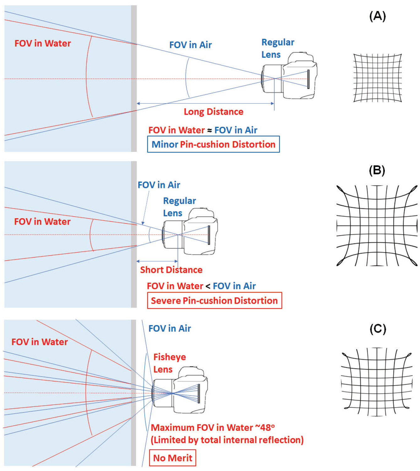
Schematic illustrations of three possible configurations in a flat port window with a camera and projected images of square grids. (A) Flat port with regular lens camera at long distance. (B) Flat port with regular lens camera at short distance. (C) Flat port with fisheye lens camera at short distance.
Schematic illustrations of two possible configurations using a dome port window with a camera and their projected images of square grids are shown in Figure 4. They are, (A) a dome port with a fisheye lens camera, and (B) a dome port with a regular lens camera. The hemispherical dome port solves the problems with a flat port. The FOV and focal length of the lens and camera system are preserved regardless of regular lens or wide-angle lenses (including fisheye lens)(Menna et al., 2016). Other issues arise when using a dome port because a spherical dome port acts as an additional optical element (a concentric lens) to the camera lens. It acts as a negative or diverging lens, making both the focal length and image distance negative. Thus, the image is formed in front of the dome (at virtual working distance (VWD)), much closer than actual distance (or working distance, (WD)) to the object. One of many side effects of a dome port is spherical aberrations. Optical rays passing through the peripheral parts and center of the dome do not converge with the same focal point because the dome port acts as a spherical lens. It causes blurring of images.

Schematic illustrations of two possible configurations using a dome port window with a camera and their projected images of square grids. (A) A dome port with a fisheye lens camera and (B) A dome port with regular lens camera.
Another undesirable optical effect of a spherical dome port is the field curvature that causes a flat object to be projected on a parabolic surface, known as a Petzval surface (Figure 6). Instead of the image sensor being flat, the consequence is that the object can appear to be not completely in focus or not uniformly sharp across the image. However, the irrefutable merits of using a dome port are the preservation of FOV and the increase of depth of field (DOF). The larger the distance between the entrance pupil and the center of curvature of the dome port, the greater the geometric distortions and chromatic aberrations (Menna et al., 2016). Despite these concerns, the usage of fisheye lens cameras with a dome port cannot be avoided for very turbid water with limited visibility, as encountered in the Yellow Sea.
A sample underwater photograph of 1 m × 1 m grid used in Taean Mado Shipwreck excavation through an 8 mm fisheye lens with a dome port camera housing. (A) Original image with barrel distortion. (B) Original image with superimposed dotted square grids. (C) Distortion compensated image with pin-cushion distorted dotted square grids, and (D) Final distortion compensated image.
For the south and east side seas of the Korean peninsula, with better visibility, unlike the very turbid Yellow Sea in the west side, we have been using a SONY A7S II camera with SONY SEL 1635Z lens (Vario-Tessar T FE 16-35 mm F/4 full frame E mount lens) in Acuatica SONY A7 SII and A7 RII housings with Acuatica 8” dome port to eliminate additional image processing steps after photographing under water since 2017.
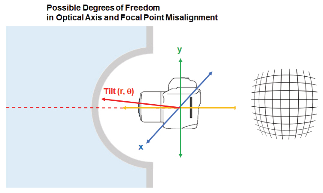
For a fisheye lens with a dome port, in principle, there are several possible degrees of freedom in the dome port and camera system, as shown in Figure 5. The non-concentricity (misalignment) of the dome port and entrance pupil can add an additional component of image distortions. A misalignment of the spherical dome port on a plane orthogonal to the optical axis of the camera lens produces decentering distortions. A misalignment along the optical axis of the lens produces a pin-cushion-type radial symmetry (either pin-cushion or barrel) distortion depending on the center of the pupil entrance relative to the center of the spherical dome. A tilt in optical axis can result in the shift of FOV and asymmetric view. If any of these misalignments are combined, the image distortion becomes very complex.
3.2. Possible Image Distortions in Underwater Photography
Normal photographs taken in air using wide angle (wide FOV) lenses such as fisheye lenses show barrel distortion. The barrel distortion is typically seen from photographs using wide angle lenses regardless of media. Underwater photographs through dome ports also show barrel distortion in lesser degree compared to normal photographs captured in air. Characteristics of barrel distortion are due to image magnification decrease with the increase of distance from the optical axis. As the name suggested, distorted images appear to be mapped around a wine barrel or a sphere. Fisheye lenses use hemispherical views to map an infinitely wide object plane into a finite image area by allowing or actively utilizing this type of distortion originated by optical lens design. In a zoom lens configuration, barrel distortion appears in the middle of its designed focal length range and is worse at the wide-angle end of the range. For underwater photographing applications with a dome port camera housing, the focal lengths of the camera lens and dome port have to be in the same position to prevent complex image distortion. Slight offsets in focal length and/or optical axis of the camera lens and the dome port can cause very complex image distortion as described in the previous section. For this reason, a variable focal length, such as 8-15 mm fisheye lens, must be used with a dome port housing designed for specific camera models in underwater photography.
Both barrel distortion and pin-cushion distortions are mathematically expressed as quadratic (power of 2) functions. The distortions increase as the square of distance from the center assuming the lens is perfectly symmetric to the optical axis. In case of complex distortion such as moustache distortion, the quartic (power of 4) term becomes significant factor. The quadratic barrel distortion is dominant near the center area, while the quartic distortion in the pin-cushion direction dominates near the edge area. Other distortions from optical axis misalignment (tilt and/or shift in any direction) of the lens and dome port housing are also possible. In practical lenses, they generally do not occur, and higher order distortions are relatively small compared to the main pin-cushion and barrel distortions, as long as optical axis and focal point are aligned. As diving depth is getting deeper, the water pressure increases by 1 atm per every 10 m from the surface. The pressure applied to the dome port housing can cause slight deformation. The slight deformation of the dome port under deep water can change focal point and optical axis misalignment. The small change can add complexity in image distortion for wide FOV fisheye lens with a short focal length.
Various image distortion compensation models have been proposed by many research groups (Wei et al., 2012; Xu, 2019; Zhang, 1999; Fitzgibbon 2001; Stack overflow, 2011; Danko, 2018). The proposed models are pretty similar to each other. For pin-cushion and barrel distortions, the distortions increase as the square of distance from the image center and they can be mathematically expressed as quadratic functions (Jung et al., 2021). In moustache distortion the quartic term becomes significant. Other more complex distortions are also possible.
The most common polynomial radial distortion model with two coefficients for expressing radial distortion is
where rd is the distance from the center of distortion in the undistorted image. The k1 and k2 are radial distortion coefficients. By neglecting quartic term, the relation between undistorted and distorted images can be simplified as
or
where ru and rd are the distance from the center of distortion in the images without and with symmetric radial distortion. α is a constant specific to the type of lens used for photography(Castillón et al., 2019; Menna et al., 2017; Kunz and Singh, 2008; Xu et al., 2019; Zhang, 1999). However, the above relations are only applicable for perfectly symmetric distortion originated from the type of lens, such as fisheye lens. If a dome port with a different focal length and/or optical axis offset between the lens and dome port is used, the image distortion cannot be properly compensated by the above approximation. If original images are altered by trimming, severe unwanted distortion will be added due to the offset from the actual center of image and the apparent center of trimmed image. Additional degrees of freedom such as asymmetric distortion and optical axis offsets must be introduced for proper image distortion compensation. We have used quadratic function to compensate image distortion with additional flexibility (i.e. ability to independently control distortion in X and Y directions and ability to compensate optical axis and focal point misalignment)(Jung et al., 2021).
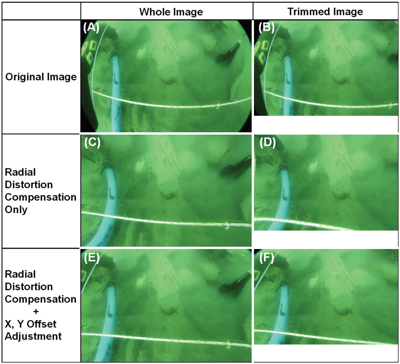
Figure 6 shows examples of radial distortion compensation of (A) whole image and (B) trimmed (or cropped) image from the Taean Mado Shipwreck excavation in the Yellow Sea from 2008 to 2010. Figure 6 (C) and (E) show distortion compensated images of whole image with radial distortion compensation only and radial distortion compensation with X, Y offset adjustment, respectively. Figure 6 (D) and (F) show distortion compensated images of the trimmed image with radial distortion compensation only and radial distortion compensation with X, Y offset adjustment, respectively. As seen in distortion compensated whole and trimmed images (Figure 6 (C) and (D)) with only radial distortion considerations, outcomes of distortion compensation are significantly different. The curvature of suction pipe (thick pipe with light blue color) and white rope (a portion of 1 m × 1 m grid) are different even after distortion compensation. By introducing additional degrees of freedom (i.e. independent adjustment of radial distortion compensation and optical axis offset and/or misalignment in X and Y directions) in distortion compensation, more realistic image distortion compensation has been achieved for both whole and trimmed images.
Figure 7 shows a sample underwater photograph of the grid used in Taean Mado Shipwreck excavation through an 8 mm fisheye lens with a dome port camera housing before and after distortion compensation. Figure 7 (A) shows as photographed original image with barrel distortion. Black areas at the four corners are characteristics of photographs taken through a wide FOV fisheye lens. The grid (supposed to be straight white lines) is photographed as latitude and longitude lines on a globe. It shows typical barrel distortion, but the grid was not photographed from the top of the grid. To evaluate and show the distortion compensation process and effect, dotted white square grids were superimposed on the original photograph as shown in Figure 7 (B). It is obvious that the grid on the photographs is neither symmetrical nor at the center. Figure 7 (C) shows the distortion compensated image of Figure 7 (B). The distortion of grid was compensated to be straight lines by applying pin-cushion distortion to the original photograph. The superimposed dotted white square grids in Figure 7 (B) became a pin-cushion distorted image in Figure 7 (C). Figure 7 (D) shows the final distortion compensated image without the superimposed grids. Since only partial horizontal grid line is shown in Figure 7 (D), the partial horizontal line near the lower left corner appeared to be bent. Since the configuration of camera with dome port housing has its own characteristics, the same image distortion compensation setting can be applied to all images from the same underwater photographing equipment. Batch processing of a series of individual underwater photographs is also possible. Video image files can also be converted into new distortion compensated video files.
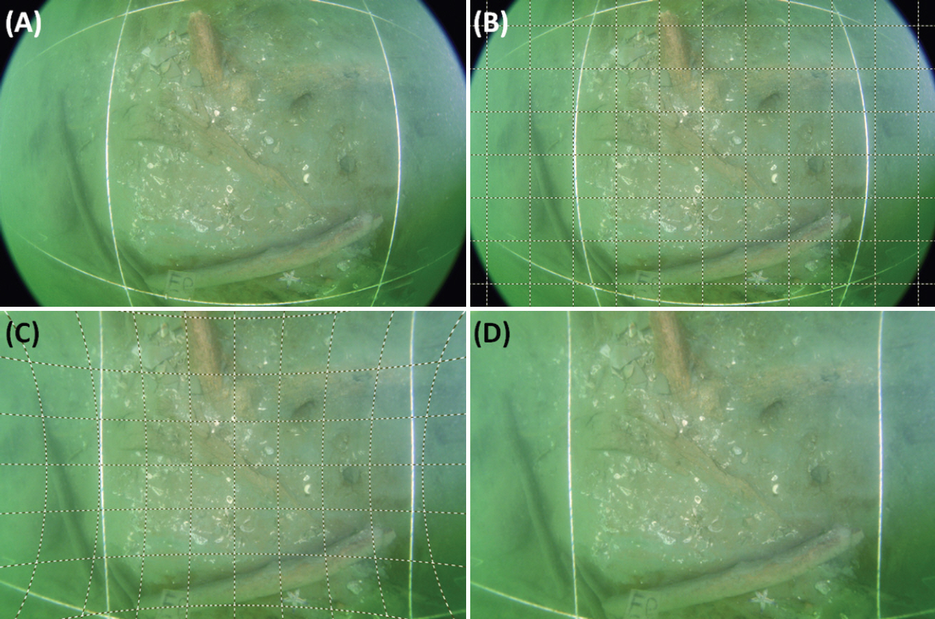
A sample underwater photograph of 1 m × 1 m grid used in Taean Mado Shipwreck excavation through an 8 mm fisheye lens with a dome port camera housing. (A) Original image with barrel distortion. (B) Original image with superimposed dotted square grids. (C) Distortion compensated image with pin-cushion distorted dotted square grids, and (D) Final distortion compensated image.
3.3. Color Shift Compensation
In general, appearance of actual color is shifted under water due to the wavelength (color) dependence of light absorption by water. Color shift becomes larger as the depth from the surface of water gets deeper due to the accumulated light absorption at different wavelengths at different rates. In turbid water, the effect is more pronounced due to poor visibility and suspended sediment, debris and living microorganisms. Even with additional lighting, certain wavelengths are absorbed and scattered by floating particles and living microorganisms. It will also distort apparent color. In turbid water, backscattering of light can also add difficulty in proper photographing. Lighting conditions such as brightness, color temperature, number of light sources, and lighting direction has to be optimized for depth and water conditions for better results. In underwater archaeology, only a small fraction of discovered artifacts is retrieved from excavation. We have to make judgments by naked eye, underwater photographs and video images with very unrealistic color information. Various photographing techniques and image enhancement techniques have been proposed for these reasons (Codevilla et al., 2015; Liu et al., 2021; Mohan and Simon, 2020; Mathivanan et al., 2019). There are other new approaches covering deep learning, color correction for 3D reconstruction and color correction algorithms comparison for underwater archaeological purposes (Mangeruga et al., 2018; Berman et al., 2021).
Figure 8 shows an example for color shift compensation of an underwater photograph during excavation preparation in 2008. As seen in the inset photograph of Figure 4 (A), color of a diver with a plastic cart cannot be clearly determined due to the enhanced green background. All pixels in digital images are composed of red (R), green (G) and blue (B) brightness information. All colors have 8-bit information and the RGB brightness range falls into 256 levels (28 = 256, 0-255 in value)(Yoo et al., 2019). RGB brightness histogram of regions of interest (ROI) can reveal the characteristics of apparent color. The ROI is selected in the middle of the photographs. Only partial area of the diver and cart are included in ROI for effective color comparison after color shift compensation. As seen in Figure 8 (A), RGB brightness histogram of ROI is very skewed. Majority of green (G) brightness ranges from 110 to 240, results in a width of 130 towards maximum brightness level. On the other hand, red (R) and blue (B) brightness distribution is very narrow, and a very dim level and a very low level of red (from 36 to 96, a width of 60) and blue (from 28 to 96, a width of 68) for color components due to selected light absorption and scattering by turbid water. To retrieve original color of ROI, the RGB histogram of the Figure 8 (A) was linearly stretched evenly for the brightness from 0 to 255. Figure 8 (B) is the result of color shift compensation results of ROI by RGB histogram adjustment (normalization). The color of the cart and diving suit became clearly recognizable.

An example for color shift compensation of an underwater photograph using RGB histogram adjustment ((A) Before and (B) After color shift compensation).
Figure 9 shows the color shift compensation results with and without barrel distortion compensation results of different ROIs indicated as red rectangles. Figure 9 (A) and (D) are the original images with different ROIs. Black areas at the four corners are obvious for pre distortion compensation. Figure 5 (B) and (E) showed color shift compensation by RGB histogram normalization in ROIs. Color shift adjustment results seemed to be different. It is because the RGB histogram data are normalized based on the RGB histogram data of individual ROIs. The ROI of Figure 9 (D) contains more green colored pixels in a wide brightness range compared to the ROI of Figure 9 (A). Figure 9 (C) and (F) show distortion compensation results of color shift compensated images. The barrel distortion was compensated by applying intentional pin-cushion distortion to the color shift compensated images. Application effects of the pin-cushion distortion can be clearly seen as clear color change boundaries in Figure 9 (C) and (F). The water pollution effects can be reduced by noise reduction and compensation for light backscattering suppression functions during color compensation.

Color shift compensation results with and without barrel distortion compensation results of different ROIs indicated as red rectangles. (A) and (D), original images with different ROIs. (B) and (E), color compensated images by RGB histogram normalization. (C) and (F), distortion compensated images after color shift compensation.
3.4. Effect of Distortion and Color Compensation Sequence
Various underwater image enhancement techniques and examples were benchmarked and reviewed (Mangeruga et al., 2018). There are many different strategies for distortion and color compensation techniques and sequences. As demonstrated in Figure 9, color shift compensation can be done first and subsequent distortion compensation using the color shift compensated image. It is also possible to do the other way around as illustrated in Figure 10. Distortion compensation can be done first and color shift compensation can be followed.

Two possible strategies of off-site image compensation (distortion compensation first or color compensation first).
We have investigated the effect of opposite sequence, i.e. distortion compensation first. As seen in Figure 10, we have selected three underwater photographs taken through an 8 mm fisheye lens with a dome port camera housing. Image distortion and color compensation were performed under optimized compensation conditions by both single image processing and batch processing. All frames of underwater video files were compensated for image distortion and color shift and successfully saved as individual images files and new video files using automatic image processing functions. As examples, three original images ((A)∼(C)) with distortion compensation ((D)∼(F)) and subsequent color shift compensation ((G)∼(I)) were shown in Figure 11. It seemed that the compensation sequence does not play significant roles in the quality of resulting images.
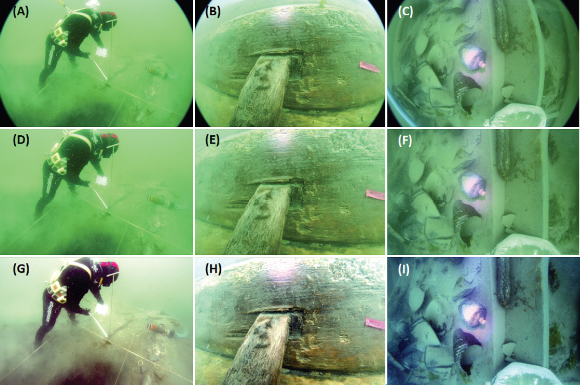
Three underwater photographs (A)-(C), after distortion compensation (D)-(F), and after color shift compensation (G)-(I). Overexposed areas in the photographs are due to the effect of non-uniform lighting and reflection from the shiny surface of objects.
In theory, performing color shift compensation first should be better in terms of image color distribution or smoothness. When distortion compensation is done first for the barrel distortion images, application of pin-cushion distortion to cancel out the barrel distortion will result in unwanted image trimming at the corners as seen in Figure 6 (D). If color shift compensation of ROI or entire image is done first, all color information is used to generate color shift compensated image as seen in Figure 9 (C) and (F). Thus, the color shift compensation for ROI should be a better option. RGB histogram normalization of very color skewed images results in non-continuous or discrete RGB histograms showing unrealistic colors. In extremely stretched cases, only a few brightness levels out of 256 brightness levels will be used. Subsequent distortion compensation steps can make the color transition more naturally by interpolation.
Figure 12 shows a reverse sequence example, i.e. color shift compensation of ROI first and distortion compensation last. No color information in ROI (A) is lost during both color shift compensation (B) and subsequent distortion compensation (C) process steps. The resulting image in the ROI is compared with the photograph taken on land after retrieval from water.
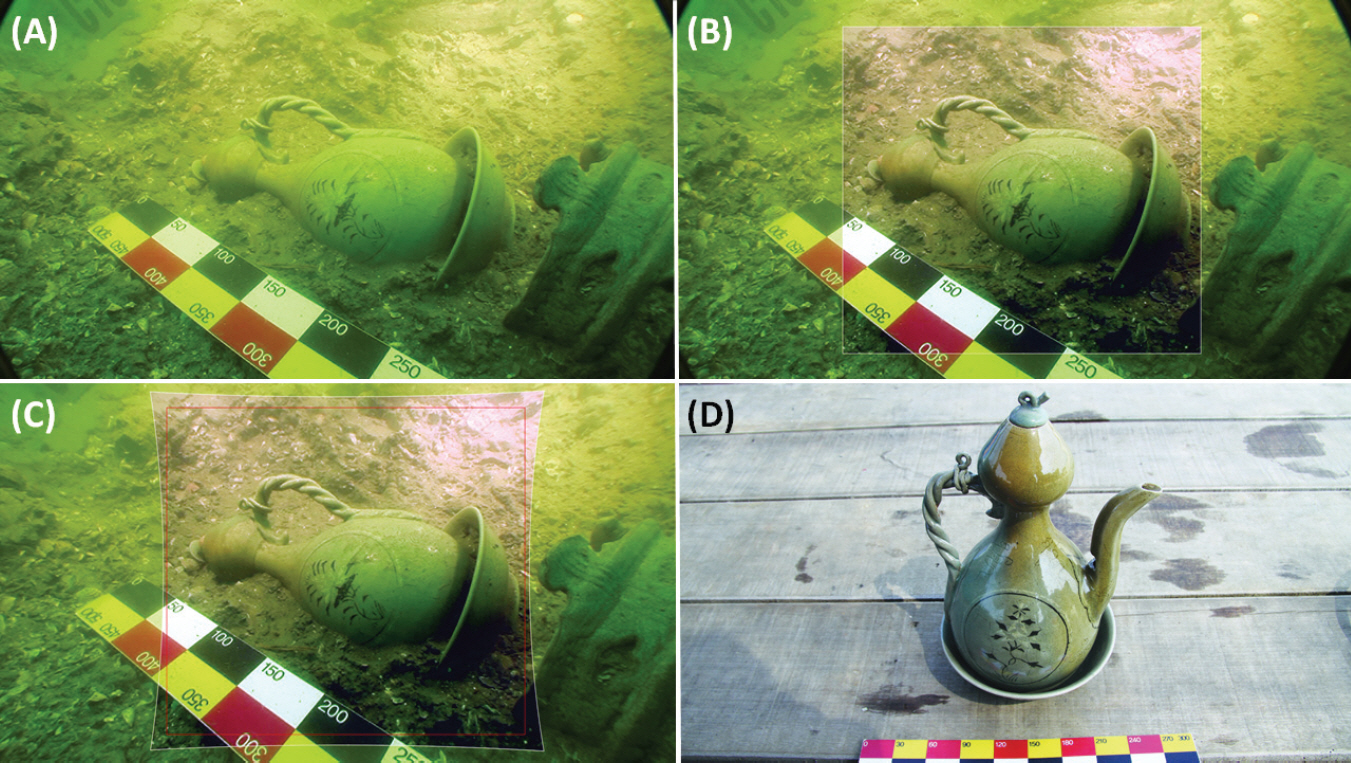
A reverse sequence distortion and color compensation example, i.e. color shift compensation of ROI first and distortion compensation last. (A) Original photograph, (B) Color compensation of ROI, (C) After distortion compensation of whole image, and (D) Photograph on land.
The color shift compensated images ((B) and (C)) are compared to the original photograph (A) and the photograph on land (D). We have used color and scale information from the color board for validating color shift compensation. Virtual grid patterns or actual grid patterns at the underwater excavation sites are also used for validating shape distortion compensation as seen in Figure 3.
3.5. Discussion
Underwater photographing equipment and techniques have been advanced significantly during the last decade. Image distortion and color adjustment techniques were available from both hardware and software solution points of view (Viduka, 2012; Pedroso de Lima et al., 2020; Menna et al., 2016; HyperPhysics, 2021; Castillón et al., 2019; Menna et al., 2017; Kunz and Singh, 2008). By adapting a dome port camera housing designed for a specific camera, most image distortion problems can be taken care of. Color shift problems in underwater photography can also be significantly reduced by adding red or orange color filters in front of the camera lens.
As introduced in the beginning of this paper, there are Yellow Sea specific regional problems of very poor visibility due to the turbidity. All underwater photographing equipment is designed and manufactured assuming reasonable visibility in relatively clear water. Advanced underwater photographing equipment cannot be an acceptable solution. We have to find practical solutions for the water condition. Customized software development is considered as one practical solution under the given circumstances. Even today, we are operating many different types of underwater photographing equipment. New equipment solutions can only take care of current and future work under reasonable environments. It cannot solve archived images from various types of photographing equipment. Excavation is an irreversible process. We have to obtain missing information by reviewing archived data. It is important to have capability to review the archived data and obtain missing information by post processing. Sometimes, we have to work with trimmed or partial images in various underwater excavation reports from other institutions.
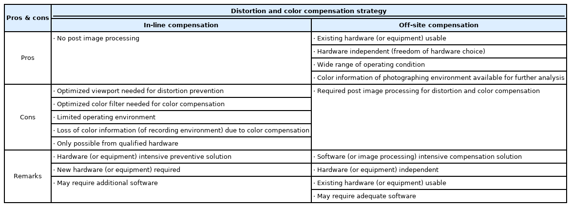
Table 1 summarizes pros and cons of distortion and color compensation strategies for underwater photography. They are basically mutually exclusive, yet complementary. In-line compensation techniques are largely equipment solutions or hardware-based solutions while off-site compensation techniques are software-based solutions. For equipment/hardware solutions, rework is not possible. Once equipment is chosen, there is no flexibility at all. Everything has to be done right at the time of work. In contrast, software-based compensation techniques are very flexible so that rework is always possible without affecting data in the archives.
4. CONCLUSIONS
In underwater archaeological study in very turbid water such as in the Yellow Sea, underwater photographing is especially challenging. In this study, off-site image distortion and color shift compensation techniques using customized image processing/analysis software is investigated as an alternative image quality enhancement method. Photographs taken during the excavation of 800-year-old Taean Mado Shipwrecks in the Yellow Sea in 2008-2011 were mainly used for testing the capability of the customized software, PicMan.
Significant enhancement in distortion and color compensation of archived images were obtained by simple post image processing. Single image processing, batch processing and video image processing have been successfully tested using images photographed through several different view ports, lenses and cameras. Post image processing is found to be very convenient and effective in distortion and color compensation of both recent and archived images from various photographing equipment models and configurations. Merits and demerits of in-situ, distortion and color compensated photographing with sophisticated equipment and conventional photographing equipment with intentional or unintentional shape and color distortions are compared. Post image processing can be a very valuable source of information compared to the archived image data. It is important to emphasize the balance between equipment/hardware-based solutions with no flexibility and software-based solutions with flexibility. Merits of off-site, post image processing for distortion and color compensation of underwater archaeological photographs and video files have been successfully verified.
Acknowledgements
All authors would like to acknowledge National Research Institute of Maritime Cultural Heritage (NRIMCH), Mokpo, Korea for providing Taean Mado Shipwreck excavation reports with archived underwater images photographed during pre-excavation survey and excavation activities. Y.-H. Jung would like to express his special thanks to his colleagues at NRIMCH for their encouragement and support during this project.
