Study on Distortion Compensation of Underwater Archaeological Images Acquired through a Fisheye Lens and Practical Suggestions for Underwater Photography - A Case of Taean Mado Shipwreck No. 1 and No. 2 -
Article information
Abstract
Underwater archaeology relies heavily on photography and video image recording during surveillances and excavations like ordinary archaeological studies on land. All underwater images suffer poor image quality and distortions due to poor visibility, low contrast and blur, caused by differences in refractive indices of water and air, properties of selected lenses and shapes of viewports. In the Yellow Sea (between mainland China and the Korean peninsula), the visibility underwater is far less than 1 m, typically in the range of 30 cm to 50 cm, on even a clear day, due to very high turbidity. For photographing 1 m x 1 m grids underwater, a very wide view angle (180o) fisheye lens with an 8 mm focal length is intentionally used despite unwanted severe barrel-shaped image distortion, even with a dome port camera housing. It is very difficult to map wide underwater archaeological excavation sites by combining severely distorted images. Development of practical compensation methods for distorted underwater images acquired through the fisheye lens is strongly desired. In this study, the source of image distortion in underwater photography is investigated. We have identified the source of image distortion as the mismatching, in optical axis and focal points, between dome port housing and fisheye lens. A practical image distortion compensation method, using customized image processing software, was explored and verified using archived underwater excavation images for effectiveness in underwater archaeological applications. To minimize unusable area due to severe distortion after distortion compensation, practical underwater photography guidelines are suggested.
1. INTRODUCTION
Underwater and maritime archaeology actively utilizes photographic and video image recording by divers and remote-controlled underwater drones for surveillances and during excavations. Because access to the archaeological sites is challenging due to the presence of water, water pressure, obstructions, and often lacks visibility, it tends to rely even more heavily on various imaging techniques compared to ordinary archaeological studies on land. All underwater images suffer poor image quality and color distortions. The distortions are mainly due to poor visibility, low contrast and blur, from waves on the water surface, presence of light scattering centers such as floating particles in water, differences in refractive indices of water and air, properties of selected lenses and shapes of viewports. Underwater photographing is not only physically challenging, but also technically challenging from equipment, image processing and application points of view.
The Yellow Sea is a marginal sea of the Western Pacific Ocean located between mainland China and the Korean Peninsula. It can be considered as the northwestern part of the East China Sea. Its name is descriptive of the phenomenon of turning its waters a golden yellow by fine sand grains from the northwest (annual Gobi Desert sand storms). It is one of four seas named after common color terms (the others being the Black Sea, the Red Sea and the White Sea) (Wikipedia, 2021). As the name suggested, the water is very turbid and visibility under water is very limited. Underwater photographing is very challenging due to the opaque nature of water.
In the Yellow Sea, the visibility under water is far less than 1 m, typically in the range of 30 cm to 50 cm, even on a clear day, due to very high turbidity. For photographing 1 m x 1 m grids for maritime heritage excavation sites under water, a very wide view angle (180° in air) fisheye lens with an 8 mm focal length is intentionally used, despite severe, unwanted barrel-shaped image distortion, even with a dome port camera housing. The effective view angle of the fisheye lens is reduced to 130°, through the dome port, under water. It is very difficult to map wide, maritime archaeological excavation sites using severely distorted images from the fisheye lens. Development of practical compensation methods for distorted underwater images acquired through the fisheye lens and practical underwater photographing guidelines are strongly desired.
In this study, the source of image distortion in underwater photographing is investigated and a practical image distortion compensation method, using image processing software, was explored. Recommendations for underwater photography from the view point of image distortion compensation are given towards maritime archaeological applications.
2. MATERIALS AND METHODS
2.1. Underwater photographs
The National Research Institute of Maritime Cultural Heritage (NRIMCH) of Korea has conducted underwater excavation in the waters of Mado island in the Yellow Sea, in the admirative district of Geunheung‒myeon, South Chungcheong Province, Korea. In this study, underwater excavation photographs taken using a fisheye lens camera resulted in severe distortions from Taean Mado Shipwreck No. 2, Underwater Excavation Report (National Research Institute of Maritime Cultural Heritage of Korea, 2011). Mado Shipwreck No. 2, from the Goryeo Dynasty, was being used to transport crops collected from the current Gochang area in North Jeolla Province to Gaegyeong, when it was shipwrecked. The selected images were used for investigating the source of distortions, distortion compensation methods, and practical and superior solutions for underwater photography solutions for maritime archaeology in waters with limited visibility, like the Yellow Sea. Figure 1 shows selected underwater excavation photographs from a fisheye lens camera with severe distortions from the Taean Mado Shipwreck No. 2, Underwater Excavation Report (National Research Institute of Maritime Cultural Heritage of Korea, 2011).

Selected underwater excavation fisheye lens camera photographs (a)∼(d) with severe distortions from Taean Mado Shipwreck No. 2, Underwater Excavation Report (National Research Institute of Maritime Cultural Heritage of Korea, 2011).
2.2. Underwater photography equipment
General photography equipment and video equipment for taking underwater images can largely be divided into two types of equipment. General digital cameras and/or video cameras for use on land are covered with a waterproof underwater housing, to make them suitable for underwater photography. Taking images during underwater excavation takes place in very difficult photographing conditions since the photography environment is much different from that of photography on land. In general, it is possible to photograph a subject up to several tens of meters clearly on land, but photography underwater involves various types of difficulties, such as reflection and scattering of light by floating objects and poor visibility. Thus, skilled photographers are required for photographing an underwater excavation. Because of these limitations, underwater excavation mainly uses a wide-angle lens that can photograph a large area at a short distance. A 15 mm (or 14 mm) wide-angle lens was used in general underwater photography. Specifically, ultra wide-angle lenses (10 mm and 8 mm fisheye lenses) were used. If photographs were taken using a fisheye lens, the distortion of the photographs is severe, but it is unavoidable at underwater excavation sites with poor visibility. In the course of excavation of Mado Shipwreck No. 2, photography was mainly done with an 8 mm fisheye lens (8 mm F3.5 EX DG Circular Fisheye lens, Sigma Corporation, Japan) on a full frame camera (EOS-450D camera, Canon Inc., Japan) with a dome port made of optical glass with anti-diffused reflection coating (PDCH-450D for Canon EOS-450D Camera, Patima Underwater Engineering Co., Ltd., Korea), because it is almost impossible to capture the entire grid within the size of 1 m on each side in a single frame with a wide-angle 15 mm lens (National Research Institute of Maritime Cultural Heritage of Korea, 2011).
2.3. Image analysis software
A novel image processing/analysis software package (PicMan from WaferMasters, Inc., CA, USA), which was originally developed for scientific and engineering applications, was customized for radial distortion compensation and correction of lens and/or optics originated distorted images. Specifically, functions for optical axis and focal point misalignment adjustment and batch image processing capability were enhanced. The amount of distortion adjustments in the radial direction, as well as individual X and Y directions, can be independently controlled. The optical axis offset in both X and Y directions can be controlled separately. The degree of freedom in distortion compensation has been significantly improved by customization for compensating underwater photography. PicMan can be used in statistical colorimetric analysis, image comparison, image highlight, digital forensics and conservation science applications. A few application examples of PicMan in the field of conservation science have been reported (Yoo and Kim, 2017; Yoo et al., 2019; Kim et al., 2019a; Kim et al., 2019b; Yoo, 2020; Yoo and Yoo, 2020; Yoo et al., 2020; Ryu et al., 2020; Kim et al., 2020; Kim et al., 2021; Lee and Wi, 2021; Yoo et al., 2021; Yoo and Yoo, 2021). For details, prior publications can be referenced.
3. RESULTS AND DISCUSSION
3.1. Origin of image distortion
In geometric optics, distortion is defined as a deviation from rectilinear projection and is specified as a percentage of the field height. Typically, ±2 to 3% distortion is unnoticed in a vision system if measurement algorithms are not used (Edmund Optics, 2021). If there is no distortion, straight lines in a scene remain straight in an image. In distorted images, straight lines in a scene become curved or out of shape as seen in Figure 1 (b) and (d). It is a form of optical aberration, but it is different from spherical aberration found in optical systems that have elements with spherical surfaces. Distortion can be irregular and can follow many patterns. The most commonly encountered distortions are radially symmetric, or approximately radially symmetric, arising from the symmetry of a photographic lens. These radial distortions can usually be classified as either barrel distortions (positive distortions) or pincushion distortions (negative distortions). Barrel and pincushion refer to the shape of the field, when distorted. In addition, improper system alignment can result in keystone distortion, which is a manifestation of parallax (Edmund Optics, 2021). Depending on literature, positive and negative distortions are defined in opposing ways. This can be very confusing. Thus, we use the words, barrel distortion and pincushion distortion, in this paper.
3.2. Underwater photography
All photographic imaging devices were designed and manufactured for use in air. For underwater photography, the imaging devices designed to be used in air must be contained in a waterproof underwater housing before underwater usage. Refractive index differences between air (n = 1.0) and water (n = 1.333) can cause other practical problems such as image enlargement/reduction, apparent depth change, image distortion, and field-of-view (FOV) narrowing, which can depend on viewport shape and materials. The refractive index of water gradually increases with salinity. The refractive index (n) of a water-salt solution with a salt concentration of 25% increases to 1.378 (Stupar et al., 2012). The refractive index (n) of sea water with a salinity of 35 ppt (parts per thousand) is known to be 1.3394 (Reef2Reef, 2021).
Figure 2 summarizes the effects of lens and viewport configurations on FOV in air and water. In air, no window or viewport is required. Since the refractive index of atmospheric air is 1.0, there is no effect on FOV or image distortion unless the window or viewport were made of thick and/or irregularly shaped, non-homogeneous optical materials. For underwater usage, imaging devices must be protected from (sea) water by placement near a clear window or viewport. The shape of the viewport can be flat or a dome. For the flat port configuration, the FOV narrows by 33% due to the refractive index difference between air and water. The angles of light incidence and refraction passing through a boundary between two different isotropic media, such as water, glass, or air can be calculated by Snell’s law (HyperPhysics, 2021). Such a configuration can result in chromatic aberrations at extreme angles. To prevent deformation and/or breakage of a flat port, the thickness and strength of the port must be selected properly, according to its working depth in water. The concentric dome port offers the same FOV as in air with minimal chromatic aberration and high mechanical strength. Slight misalignment of the optical axis and/or focal distance can cause unwanted systematic image distortions. Zoom lenses with variable focal points should not be combined with dome ports for this reason. A fixed focal lens or a fisheye lens should be used with the dome port at the aligned axis and position. An 8 mm fisheye lens can generate severely distorted images covering 180° in air. The same fisheye lens can only cover up to 130° in water due to the shape of dome port. It also generates severely distorted images covering the 130° FOV in water.

Effects of lens and viewport configurations on FOV in air and water. FOV; field-of-view.
3.3. Requirement for underwater photography in limited visibility
In clear water, an object can be visible up to 100 m. Photographic images fade to blue in 40 m to 60 m. For turbid water in the Yellow Sea, visibility is significantly limited to far less than 1 m. To photograph 1 m x 1 m grids using a 4:3 full frame camera at a distance of 0.5 m, a FOV of >90° is required (Figure 3). Considering ∼33% FOV reduction through a flat port in water, a much wider FOV is required. The only possible option is to use a very wide 8 mm fisheye lens with a dome port as shown in Figure 2. This will give approximately a 130° FOV under water. It will allow wide angle photography at close distances even though the resulting images are severely distorted as shown in Figure 1.
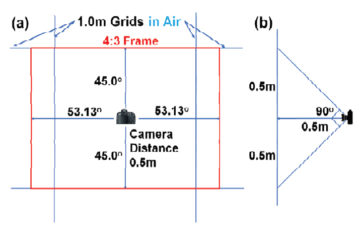
FOV required to photograph a single 1 m x 1 m grid at a distance of 0.5 m in air. FOV; field-of-view.
3.4. Types of image distortion
There are three major types of image distortions. They are pincushion distortion, barrel distortion, mustache distortion (a combination of pincushion distortion and barrel distortion) and keystone distortion from parallax.
Pincushion distortion is typically observed from the underwater photography taken through a flat port window using a regular lens. Image magnification increases with increased offset from the optical axis. Lines that do not go through the center of the image are bowed inwards (towards the center of the image), like a pincushion.
Barrel distortion is typically seen from photographs using wide angle (FOV) lenses through dome ports underwater. Photographs taken using wide angle (FOV) lenses in air also show barrel distortion. Image magnification decreases with increased distance from the optical axis. Images appear to be mapped around a wine barrel or a sphere. Fisheye lenses use hemispherical views to map an infinitely wide object plane into a finite image area, actively utilizing this type of distortion. In a zoom lens, barrel distortion appears in the middle of its focal length range and is worse at the wide-angle (wide FOV) end of the range.
Mustache distortion is a mixture of both pincushion distortion and barrel distortion. It is a complex distortion, but not rare. It typically shows barrel distortion near the image center and gradually turns into pincushion distortion towards the edge of image. It makes horizontal lines in the top half of the frame look like a handlebar mustache, as suggested by the name of the distortion.
Beside these geometric radial distortions, there is wavelength (color) dependent radial distortion called “lateral (radial) chromatic aberration". This can cause colored fringes in high-contrast areas at the edge of the image. This is different from axial (longitudinal) chromatic aberration (typically purple fringing) throughout the field.
3.5. Software-based distortion compensation
Pincushion and barrel distortions are mathematically expressed as quadratic (power of 2) functions. The distortions increase as the square of distance from the image center. In mustache distortion the quartic (power of 4) term is significant. In the center, the quadratic (power of 2) barrel distortion is dominant, while, at the image edge, the quartic (power of 4) distortion in the pincushion direction dominates. Other distortions are also possible in principle. In practical lenses, they generally do not occur, and higher order distortions are relatively small compared to the main pincushion and barrel distortions. Various distortion compensation models have been proposed by many research groups (Hughes et al., 2008; Dhane, 2012; Wei et al., 2012; Leng, 2016; Lee et al., 2019; Xu, 2019). The proposed models are pretty similar as a whole.
Figure 4 shows mathematically generated barrel distortion (positive distortion) and pincushion distortion (negative distortion) with and without optical axis offsets, to undistorted grid patterns and clock images. When a flat is used with a regular lens under water (Figure 2, upper right), pincushion distortion occurs. As the distance between camera lens and the flat port is reduced, the pincushion distortion becomes larger. If wide angle lenses, such as fisheye lenses, are used with a dome port at the common focal point (Figure 2, two bottom images), barrel distortion will occur regardless of media (i.e. water or air). As the FOV of fisheye lens increases, the barrel distortion becomes larger. Any offset between focal point, and/or optical axis, of the dome port and camera lens can result in asymmetric complex distortion. Figure 5 shows (a) a rectangular graph paper image, (b) simulated photographed image through fisheye lens (intentionally distorted image using software) and (c) a compensated image using software. A perfect image, without any distortion, was used to simulate the intentional addition of barrel distortion and application of pincushion distortion to the intentionally barrel distorted image for recovery. As seen from Figure 5 (c), a distorted image from a fisheye lens can be compensated using software. The center region (about 50% of width and height of full frame, indicated by a red rectangle) can be successfully compensated. Four red dots in Figure 5 (b) are radially stretched to the corner of the red rectangle in Figure 5 (c) by mathematical compensation by software without considering focal point and optical axis offsets.

Mathematically generated barrel distortion (positive distortion) and pincushion distortion (negative distortion), with and without optical axis offsets, applied to undistorted grid patterns and clock images.
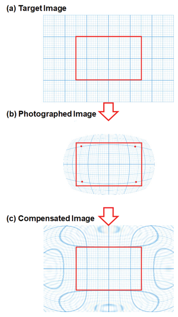
(a) A rectangular graph paper image. (b) Simulated photographed image (intentionally distorted image using software) and (c) A compensated image using software.
To evaluate the applicability of the same distortion compensation process, it has been applied to an underwater photograph from Taean Mado Shipwreck No. 2, Underwater Excavation Report (National Research Institute of Maritime Cultural Heritage of Korea, 2011) (Figure 6). The FOV of the underwater image by an 8 mm fisheye lens through a dome port is approximately 130°. Rectangles and grid lines in Figure 6 are inserted to demonstrate the degree of compensation. The red rectangle and blue rectangle in Figure 6 (a) show the maximum 3:2 full frame area of the image and maximum usable area after compensation. The white rectangle and blue rectangle in Figure 6 (b) are the 3:2 full frame image size (the same as Figure 6 (a)) and represent maximum usable area after compensation. A slight off set of optical axes between the fisheye lens and the dome port can be noticed from the compensated image.
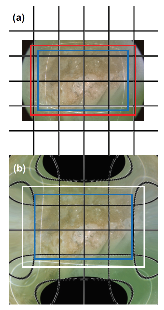
(a) underwater photograph from Taean Mado Shipwreck No. 2, Underwater Excavation Report (National Research Institute of Maritime Cultural Heritage of Korea, 2011) and (b) compensated image (Rectangles and grid lines are inserted to demonstrate degree of compensation).
3.6. Discussion
In an ideal case, image distortion in photographs through a fisheye lens should be symmetric. Due to the interference with a dome port with fisheye lens for underwater photography, distortions are not as symmetric as we would expect. For illustration purpose, we have summarized one original underwater photograph using an 8 mm fisheye lens and distortion compensated images in three different ways (Figure 7). The original photograph shows the very typical signature of a fisheye lens photograph. It had black regions at four corners. Fisheye lens photographs taken on land show a perfect circle in the full frame image. Due to the FOV narrowing under water and the interference with the dome housing, photographic images cover the majority of a full-size frame. To evaluate the optical axis alignment between the fisheye lens and dome port, the black areas at the corners were measured. They were 12,306 pixels, 10,189 pixels, 9,373 pixels and 10,401 pixels from top left (in the clockwise direction). This suggests that the optical axis of the fisheye lens is slightly misaligned in the bottom right direction relative to the optical axis of the dome port. This will cause nonlinear, complex image distortion. It cannot be compensated by a simple operation in the radial direction, as seen in Figure 7 (b). If we allow independent compensation in X and Y directions, without X and Y offsets (translations), distortion will improve slightly as shown in Figure 7 (c). When we introduce the optical axis offsets in the X and Y directions, the image compensation looks much better and more natural. It is important to have higher degrees of freedom in image distortion compensation for underwater fisheye lens photographs.
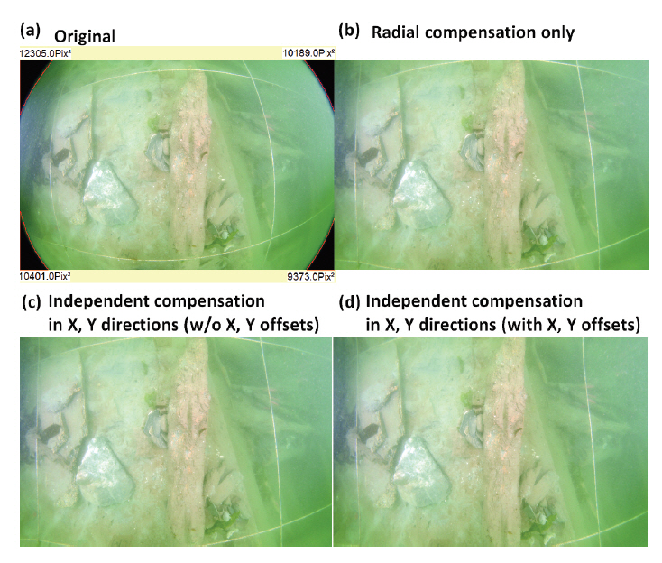
Effect of distortion compensation methods. (a) Original image. (b) Radial compensation only. (c) Independent compensation in X, Y direction without offsets, and (d) independent compensation in X, Y direction with X, Y offsets.
Once the lens and a dome port configuration are fixed, systematic distortion is applied to all underwater images photographed using the same hardware. Thus, the same distortion compensation algorithms can be applied to compensate the distorted underwater images. Figure 8 shows, as photographed, three sample underwater images with severe barrel distortion before and after distortion compensation using software. The compensation results are satisfactory. For mapping wide underwater excavation sites in limited visibility, short distance photography with the aid of a fisheye lens and a dome port cannot be avoided. Unfortunately, all images are heavily distorted and cannot provide realistic area maps by placing distorted images side by side. Area map by arranging distortion compensated images, after cropping uncompensated areas, can provide more realistic images of underwater excavation sites.

Three sample underwater photographs with barrel distortion, after radial distortion compensation only, and after additional compensation for optical axis offset in X and Y direction using software.
Since only 70% of 130° effective FOV underwater images are usable after distortion compensation, it is better to provide guidelines for usable areas of image on a viewfinder of the photographic device. This will be very useful as shown by the blue rectangle in Figure 9. To generate more accurate underwater excavation site maps under limited visibility, smaller grids such as 0.5 m x 0.5 m grids may be more useful and practical, considering the extra work and after photographing and mapping accuracy.
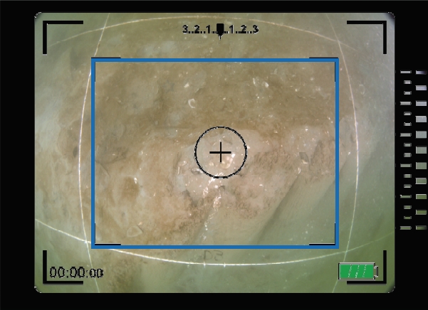
Guideline (blue rectangle) for usable area of image on a viewfinder of the photographing device.
By using a batch processing function of the image processing software, PicMan, many images can be automatically compensated and the compensated images can be exported. The same technique can be applied to video image files. Severely distorted video image files can be converted into compensated image files. If the same compensation algorithms are integrated with underwater video cameras, compensated images can be recorded. This will eliminate unnecessary extra steps on land after video recording underwater.
4. CONCLUSION
Like all archaeological activities on land, underwater archaeology also relies heavily on photographing and video image recording during surveillances and excavations. All underwater images suffer some degree of poor image quality and distortion due to poor visibility, low contrast and blur, differences in refractive indices of water and air, properties of selected lenses and shapes of viewports. In the Yellow Sea (between mainland China and Korean peninsula), the visibility underwater is far less than 1 m, typically in the range of 30 cm to 50 cm, even on a clear day due to very high turbidity arising from geological characteristics such as annual Gobi Desert sand storms from the northwest.
For photographing 1 m x 1 m grids underwater, a very wide view angle (180°) fisheye lens, with an 8 mm focal length and a dome port camera housing, is intentionally used despite unwanted and severe barrel-shaped image distortion. The effective FOV is approximately 130° underwater. It is very difficult to map wide underwater archaeological excavation sites by combining severely distorted images. Development of practical compensation methods for distorted underwater images, acquired through a fisheye lens, is highly desired.
In this study, the source of image distortion in underwater photography is investigated. A practical image distortion compensation method using image processing software, PicMan, was explored and verified for effectiveness in underwater archaeological applications. Batch processing of image distortion compensation and streaming line video image compensation techniques are proposed.
Providing guidelines on a viewfinder of the photographic device to photographers for easy recognition of usable area of image is recommended. Use of smaller grids, such as 0.5 m x 0.5 m, is also suggested as an alternative, considering the limited visibility of many underwater photographic environments. For more accurate image distortion compensation, characterization of underwater photography equipment in experimental underwater environments using grids, is highly recommended.