


1. INTRODUCTION
The majority of sculptures of the modern and contemporary era use representation techniques based on realistic descriptions such as head, nude or human figure sculptures, which were emphasized in the educational curriculums of Japan. Since the majority of pioneers of modern sculpture were educated in Japan, works of the maestros of the Ancient and Renaissance eras were used thoroughly as the foundation for their replication of plaster sculpture or the drawing of the human body due to the influence of the education that they had. Kyung Seung Kim (1915 ~ 1992), a First-generation sculptor from Korea, testified that lessons were given with a focus on producing human model works by moving from the head, bust and life-sized statues with the use mainly of clay and plaster (Kwon et al., 2017).
In particular, plaster is easy to handle and allows the obtaining of exquisite expression of texture, and precise dimensions due to its low expansion and contraction levels. In addition, it is readily available. As such, although it is used extensively by all levels of artists ranging from beginners to experts, many modern sculptures that had been produced were lost at the time of the Korean War due to its fragility towards physical impact and difficulty of transportation, etc. In recent years, plaster sculptures are frequently packaged and transported for purposes such as exhibition and rental, etc. It is anticipated that damages will occur due to impacts and vibrations applied to the works during the process. In particular, in the case of life-sized plaster sculpture, impact and vibration delivered to the bottom section causes cracks and breakages, thereby leading to structural damage (Kwon et al., 2017). In addition, given the trend of concerns for the means of safe prevention of disasters such as earthquakes for cultural heritage since the occurrence of an earthquake in Gyeongju in 2016, further studies are necessary.
Diversified optical technologies such as photography and microscopes, or non-destructive safety diagnosis methods including X-ray, CT, ultrasonographic analysis and thermal image cameras, are used to investigate the accurate state of, or extent of damages to such modern and contemporary sculptures. Furthermore, preparations are made for damage that could be incurred in the future by establishing a DB including information and images of important original artworks in possession in the format of 3D data.
Overseas countries have already been actively pursuing studies using finite element analysis (FEA) in order to assess the structural stability of structural cultural assets and heritage. For example, evaluation of the stresses and deformation imparted on structures such as the Equestrian Statue o f Marcus A urelius of Italy has b een d one s ince t he 1990’s by using FEA in order to improve the accuracy of non-destructive investigation (X-ray) of the cracked sections (Bici et al., 2018). In addition, structural analysis using FEM was executed to diagnose the safety of the statue of David by Michelangelo and the Barletta statue (Borri and Grazini, 2006; Alfio et al., 2022). Static safety diagnosis of the weight of each of the subsidiary materials of outdoor modern cultural heritage items including the Paci-type steam train and a Busan streetcar were made in Korea (Cho et al., 2021). Finite element analysis used here utilizes the system of computing the stress and deformation of the structure by changing the 3D digital image scanned subject into a numerical analysis model and by means of diversified constraining and load conditions.
With ‘Eve 58-1’(1958), a sculpture by the artist Man Lin Choi (1935 ~ 2020) as the subject of this study, it has thin arms and legs along with bulging abdomen and has highly vulnerable proportional structure in comparison to its height of 133 cm. ‘Eve 58-1’ is the first work of the Eve series and won the grand prize in the 7th National Art Exhibition (1958) and could be deemed a monumental work by the artist through which he joined the art circle upon graduation from university in 1958. In this study, a structural stability evaluation using FEA is executed on ‘Eve 58-1’, a work by the artist Man Lin Choi, to assess the structural vulnerability of the sculpture to prepare for possible damage in advance and proposed standards for the safe transportation and handling of the sculpture are presented.
2. THEORETICAL BACKGROUND
2.1. CAE(Computer Aided Engineering)
CAE is a program capable of executing the virtual simulation of the designed structure by using computers and is used widely, not only in the areas of machines, but also in all industrial areas as it is possible to verify the design and deduce improvements of structure. It is possible to reduce cost through realization with the program without directly producing and demonstrating the mounting post, which is expensive avionics equipment, in the design stage (Lee et al., 2010) and it can be utilized efficiently in various aspects in the event of playing the role of improving the stability through optimization design and modeling by checking the vulnerable sections and stress applied in accordance with the load to the legs of the chair (Nam et al., 2015), etc.
To apply CAE, consider and reflect on the physical material properties and boundary conditions of the structures. For physical material properties, modulus of elasticity, Poisson’s ratio and density, etc. obtained through material tests are used. Boundary conditions can be classified into constraining conditions and load conditions, and a wide range of boundary conditions, including displacement, force, pressure and temperature, can be endowed by reflecting the environment applied to the actual structure.
At this time, computational processes of the structures include the computation of stiffness through the configuration of the structures and applied physical material properties and the deformation of the structures is computed by means of the inputted constraining conditions and load conditions. Deformation can be divided by the original length to compute strain and the stress of the structures is finally computed. Structural safety of the structure is evaluated by comparing the diversified resultant values computed by means of CAE with safety regulations or the destruction standard values (deformation, yield strength and tensile strength, etc.) of the materials applied.
2.2. Finite element method
Finite element method (FEM) is a numerical analysis technique of finding the solution by dividing the model produced with CAD into a limited number of elements and approximating the computational equation for each element by means of a linear algebraic equation. Studies aimed at the improvement of stability, accuracy and efficiency are continuing in the FEM domain with the improvement of stability among these 3 elements as the ultimate goal.
The basic process of FEA meshing the domains of the problem into finite elements before composing equipment for each individual element (in matrix format). Then, after having composed the equation for the entire system by assembling the mathematical formula of each element, solve the equation for computing the displacement at each node. After having computed various displacement, strain and stresses, illustrate the results through visualization (Lee, 2020) (Figure 1).
In this study, the physical structure of the artwork is analyzed through the provision of objective data following FEM conversion of ‘Eve 58-1’ for application to the improvement of stability through realization by means of CAE.
3. STUDY METHOD
3.1. Material analysis
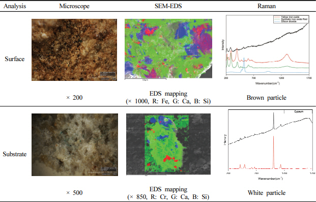
The purpose of this study is to support monitoring for safety diagnosis and preventive preservation through the utilization of digitization technology by acquiring scientific information on and current status of the sculptures. Therefore, Table 1 was referred to the results of the preceding study that executed microscopic, SEM-EDS and Raman analysis, etc. to secure primary information on the materials used for the works (Shin et al., 2022).
As the results of microscopic observation of the surface layer, yellow, brown, black, white and transparent particles are in irregularly mixed state and, as the results of SEM-EDS analysis, Ca (Calcium) and S (Sulfur) are detected at high strength overall while Si (Silicon) is detected intensively within relatively large crystalline particles. As per the results of Raman analysis, a weak peak is confirmed in the vicinity of 217, 282 and 514 cm-1, in the case of brown surface layer particles, which corresponds to the characteristic peaks of Iron(III) oxide monohydrated (Fe2O3⋅H2O) and Iron(III) oxide(Fe2O3).
As the results of microscopic observation of the substrate layer, white and transparent particles account for the majority with the state of irregularly mixed small quantity of black and brown particles. Meanwhile, the results of SEM-EDS analysis display the detection of Ca and S at high strength for the white portion in comparison to the surface layer with the tendency of localized detection of Si, Al and K, etc. according to the location of analysis. As the results of Raman analysis, characteristic peak of gypsum is confirmed in the vicinity of 1,008 cm-1 for the white particle in the substrate layer. It was possible to confirm that ‘Eve 58-1’ was produced by using the surface coating method of having applied coloring agent in the iron oxide range to the top of plaster since the cross-section can be visually distinguished into a brown surface layer and a white substrate layer.
3.2. 3D modeling through digital imaging
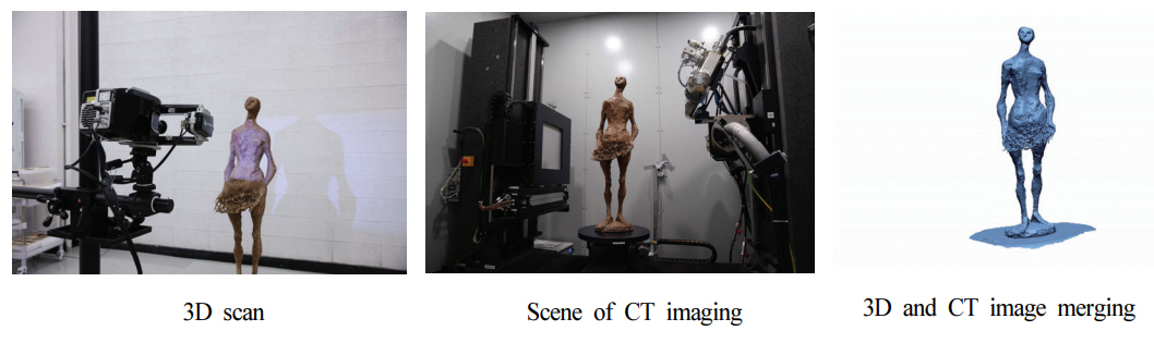
3D scanning of the exterior of the work was executed for the internal and external structural safety diagnosis of the sculpture (AICON Stereo SCAN NEO R16, Hexagon, SWE) and X-CT scanning X-CT (CR Moduler, YXLON, DEU) was executed to check the internal structure. Then, editing to merge the overall 3D scan image and CT image of the work was executed. At the same time, after having converted the merged image into a compatible extension file, internal and external images were 3 dimensionally embodied by using Geomagis Design X, a software of 3D system (Figure 2).
3.3. Digital image conversion and finite element modeling settings
Each of the acquired overall internal and external images of the ‘Eve 58-1’ sculpture were merged through CT and 3D scanning, and clean-up work was carried out by using Ansys SpaceClaim. Through this process, the facet domain of the model was reduced and sharp domains were corrected into a 3D model for which a finite element model can be generated. In order to execute the finite element modeling for structural analysis, solid conversion of the facet model is necessary.
At this time, it was ensured that appropriate mesh density could be applied since too many meshes can excessively increase time taken for analysis without major effect on the analysis results. Relatively softer surface figuration in comparison to the existing original model was confirmed and it was possible to visually confirm that the number of facets has been reduced and sharp domain has been corrected in the detailed figuration that compared the existing merger model and solid conversion model of the thorny bush expressed at the center of the sculpture (Figure 3).
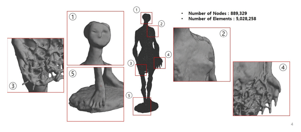
Finite element modeling setting of the facet model was generated by utilizing the meshing function of Ansys Mechanical. Tetrahedron elements are applied since the ‘Eve 58-1’ model has a relatively complex configuration and mesh was generated by using the Patch Independent method since the external surface has highly extensive surface divisions. Figure 4 illustrates the finite element modeling of ‘Eve 58-1’ and was modeled to ensure thorough expression of the maximum characteristics of the structure by applying tight mesh size to enhance the accuracy of analysis.
3.4. Physical material property values and boundary conditions
To apply physical material properties to an FEM model, the preceding study was conducted for the analysis of physical properties of the materials used in ‘Eve 58-1’. Plaster (CaSO4) is the main material for the substrate layer of the sculpture and it is presumed that soil-borne minerals such as quartz, etc. were artificially mixed or some impurities have been mixed to improve the hardness and durability of relatively weak plaster.
For the physical properties of plaster used for ‘Eve 58-1’, the physical material property library (Ansys Granta) that Ansys holds was applied and the material density was reflected in consideration of the actual weight of the paster sculpture at 14.8 kg (Table 2). For the resultant value, the displacement value that changes by being induced to the structure subjected to external force was compared with numerically quantified stress, which is the force for the unit area generated within the deformed object.
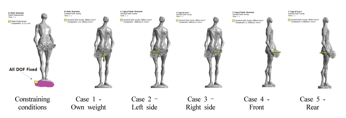
As the boundary conditions for the execution of structural analysis of ‘Eve 58-1’, plaster conditions that restrain all the degrees of freedom at the floor of the statue were generated. For the load conditions, acceleration conditions for each direction were applied to compute its own weight and force of inertia due to spontaneous acceleration that can occur at the time of transporting plaster statue. Acceleration conditions for each direction of 9.81 m/s2, which is the same as its own weight, were applied (Figure 5).
It was possible to analyze the structure as follows by substituting the Poisson’s ratio of 0.273 for the tensile strength in accordance with the material ratio under the condition of the modulus of elasticity of 6,000 MPa of the plaster itself.
4. RESULTS OF FINITE ELEMENT ANALYSIS
In order to evaluate the structural safety of ‘Eve 58-1’ by the artist Man Lin Choi, physical properties similar to those of the plaster used for the work were reflected. Since the sculpture is transported by being hand lifted after having placed the work on pallet, acceleration was applied in the direction that will have the most force at the time of transportation. Directions of acceleration of force are divided largely into static (lowering) and kinetic (left, right, front and rear directions) structural analysis, and the results of structural analysis after application are summarized in the Table 3 below.
4.1. Results of static structural analysis of ‘Eve 58-1’
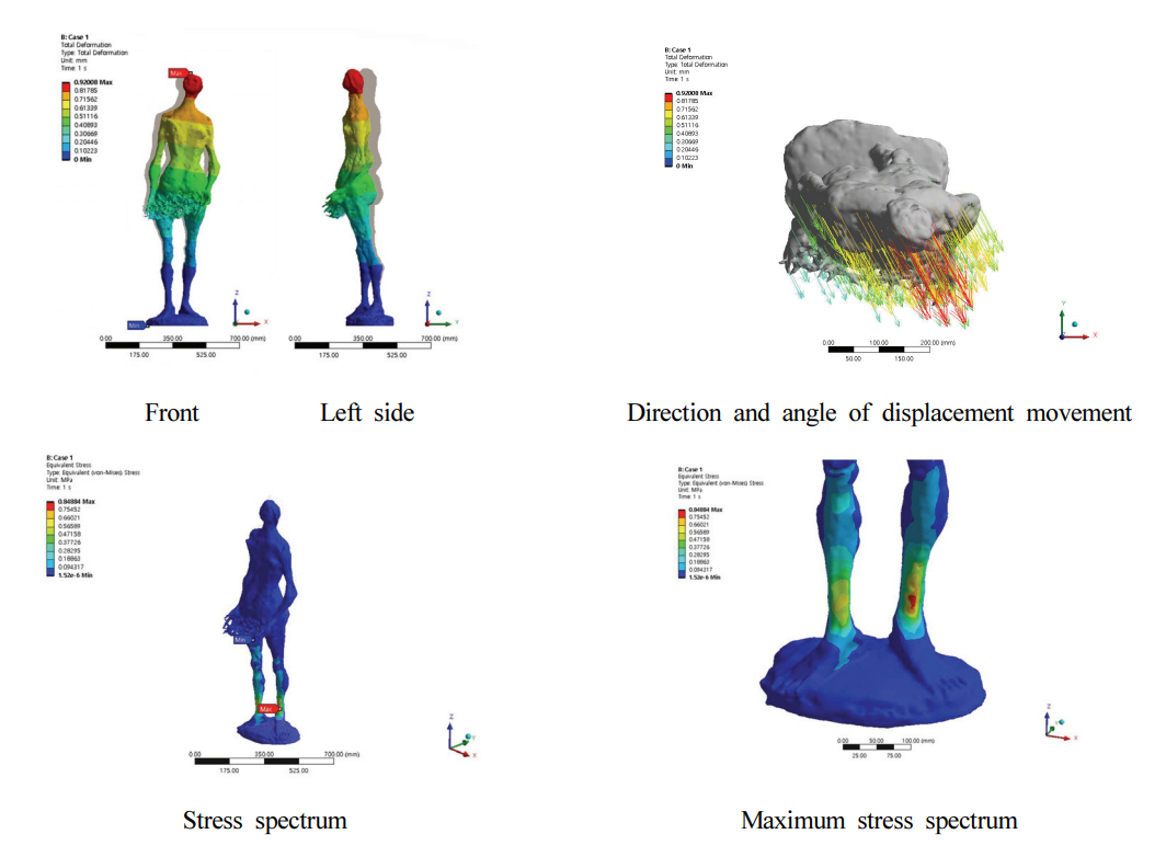
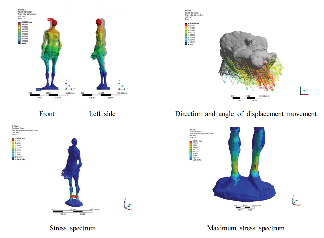
When acceleration is applied to the top of the work → the bottom (vertical direction) with Z-axis as the reference, displacement is manifested in the frontal diagonal direction at the angle of ∡29° with Y-axis as the reference at each position. Among the displacements, it was possible to confirm that the maximum displacement of 0.92 mm occurred at the head section.
As a result of the confirmation of the stress value, compression stress as the key stress is distributed in the Z-axis direction of thigh → knee → ankle, and focused on the front of the left ankle marked with red color (Figure 6). It was confirmed that the left angle section where the stress is concentrated has a maximum stress value of 0.85 MPa.
4.2. Results of kinetic structural analysis of ‘Eve 58-1’
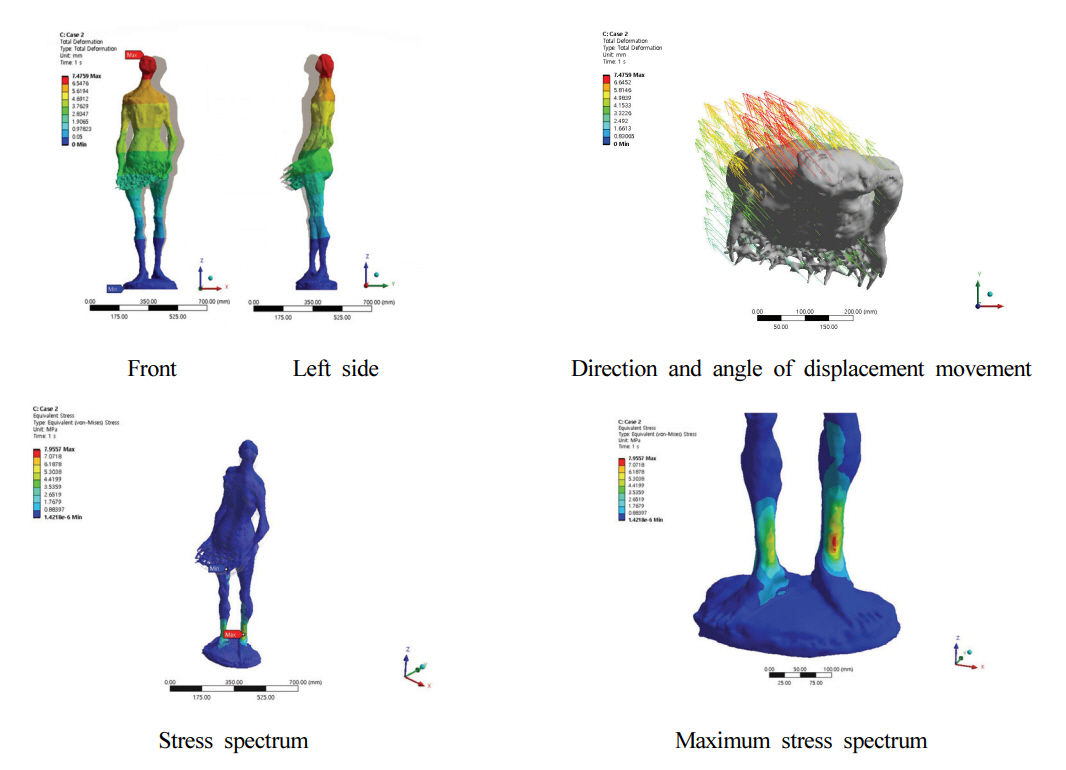
When acceleration is applied to the work from right → to left (in a horizontal) direction, which is negative (-), with X-axis as the reference, displacement is manifested in the frontal diagonal direction at the angle of ∡42° with Y-axis as the reference at each position. Among the displacements, it was possible to confirm that the maximum displacement of 7.48 mm occurred at the head section. As the results of the confirmation of stress value, compression stress as the key stress is distributed in the Z-axis direction of the thigh → knee → ankle, and focused on the front of the left ankle marked with a red color. It was confirmed that the left angle section where the stress is concentrated has a maximum stress value of 7.96 MPa (Figure 7).
When acceleration is applied to the work in a left → to right (horizontal) direction, which is positive (+), with X-axis as the reference, displacement is manifested in the rear diagonal direction at the angle of ∡42° with Y-axis as the reference at each position. Among the displacements, it was possible to confirm that the maximum displacement of 7.48 mm occurred at the head section. As the results of the confirmation of stress value, compression stress as the key stress is distributed in the Z-axis direction of thigh → knee → ankle, and focused on the front of the left ankle marked with a red color. It was confirmed that the left angle section where the stress is concentrated has a maximum stress value of 7.96 MPa (Figure 8).
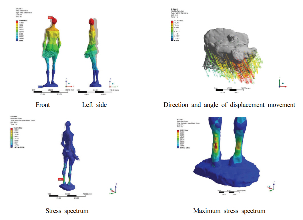
When acceleration is applied to the work from the rear → the front (horizontal) direction, which is negative (-), with Y-axis as the reference, displacement is manifested in the frontal diagonal direction at the angle of ∡27° with Y-axis as the reference at each position. Among the displacements, it was possible to confirm that the maximum displacement of 13.45 mm occurred at the head section. As the results of the confirmation of the stress value, compression stress as the key stress is distributed in the Z-axis direction of the thigh → the knee → and the ankle, and focused on the back of the left ankle marked with a red color. It was confirmed that the left angle section, where the stress is concentrated, has a maximum stress value of 10.62 MPa (Figure 9).
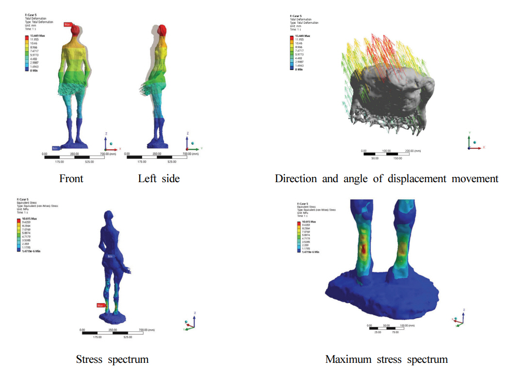
When acceleration is applied to the work in the front → to the rear (horizontal) direction, which is positive (+), with Y-axis as the reference, displacement is manifested in the rear diagonal direction at the angle of ∡27° with Y-axis as the reference at each position. Among the displacements, it was possible to confirm that the maximum displacement of 13.45 mm occurred at the head section. As the results of the confirmation of the stress value, compression stress as the key stress is distributed in the Z-axis direction of the thigh → knee → ankle, and focused on the back of the left ankle marked with a red color. It was confirmed that the left angle section where the stress is concentrated has maximum stress value of 10.62 MPa (Figure 10).
5. DISCUSSIONS
As the results of structural analysis after having applied its own weight and acceleration in each direction (Table 3), the maximum displacement occurred in the top head section with the initial position as the reference. As the results of the stress analysis, maximum stress occurred in the left ankle section. However, a value smaller than the maximum compression strength of plaster of 17 Mpa manifested, thereby confirming that it is within the current structural safety range. The same left-right value and front-rear value are obtained because they have the same structural stiffness with the only difference being in the direction of the load applied.
When its own weight, and left-right and front-rear directional accelerations are applied to the work, the biggest displacement manifested in the front direction tilted at the angle of ∡27°. A t this t ime, s ince t he work can be moved to the direction in which the maximum displacement manifests, analysis was executed by applying acceleration in the frontal diagonal direction at the angle of ∡27° with the Y-axis as the reference where the maximum displacement manifests. Table 4 illustrates the analysis results, and it was possible to confirm manifestation of the maximum displacement of 15.24 mm at the head section and maximum stress of 12.46 Mpa at the left ankle section that supports the load. The corresponding results illustrate that the left ankle section is most vulnerable at the time of application of pressure and is the section for which maximum precautions need to be exercised at the time of transporting the work.
6. CONCLUSION
With the emergence of the Fourth generation industrial revolution in the current era, technological convergence between different industries is becoming essential. In particular, it has become very important to adapt to the changes first as the ‘First Mover’ based on flexibility and agility, which are key competitive factors in the current era of the Fourth generation industrial revolution (Lee, 2019). Although diversified digitalization areas are being applied to and utilized by the preservation sciences for cultural heritage in accordance with the changes of the time, it is focused only on digitization or reproduction of the visual characteristics of such cultural heritage in Korea.
In the current era of the Fourth generation industrial revolution, there is a need for the conservator to personally confront artworks and expand the area of preservation processing to digitized preventive preservation processing that realizes a virtual future through diversified convergent technologies for the aspects that humans cannot predict by transcending the realm of analogue preservation processing to enhance the durability of the artworks. The structural safety diagnosis utilizing the CAE program for modern and contemporary sculpture summarized in this study is an example that can be presented as an area of digitized preservation processing.
Internal and external aspects of ‘Eve 58-1’, an artwork by the artist Man Lin Choi, were turned into a database through 3D and X-CT scanning, and structural safety diagnosis and predictive simulation analysis of the artwork was executed by presuming the application of acceleration to artwork through 3D CAE program utilized in industrial design. As a result, it was possible to quantify the fact that the maximum impact is applied to the left ankle and maximum displacement occurs in the head section through acquisition of objective values thereof.
Since stress is generated at the ankle, even with minute impacts and vibrations from the surroundings, by means of minimizing vibration at the top portion of the artwork is required for the future along with continuous monitoring. In addition, there is a need to review the installation of support and production of crates for exclusive use in storage in order to ensure that minimum load at the bottom of the sculpture occurs at the time of transporting the artwork.
Although there is a need to predict diversified situations and apply hypothesis in order to implement preventive preservation that transcends the domain of preservation through direct handling of the artworks, limitations have been placed only on theories until now.
However, it was possible to objectively verify the ambiguous thought that stress can occur in the ankle even through minute impacts and vibrations in the surroundings through finite element analysis as technologies are advancing. It is anticipated that study performances capable of realizing this goal further by applying more diversified technologies to preservational processing can be achieved, beginning with the results of this study.